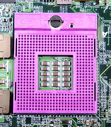
Socket P
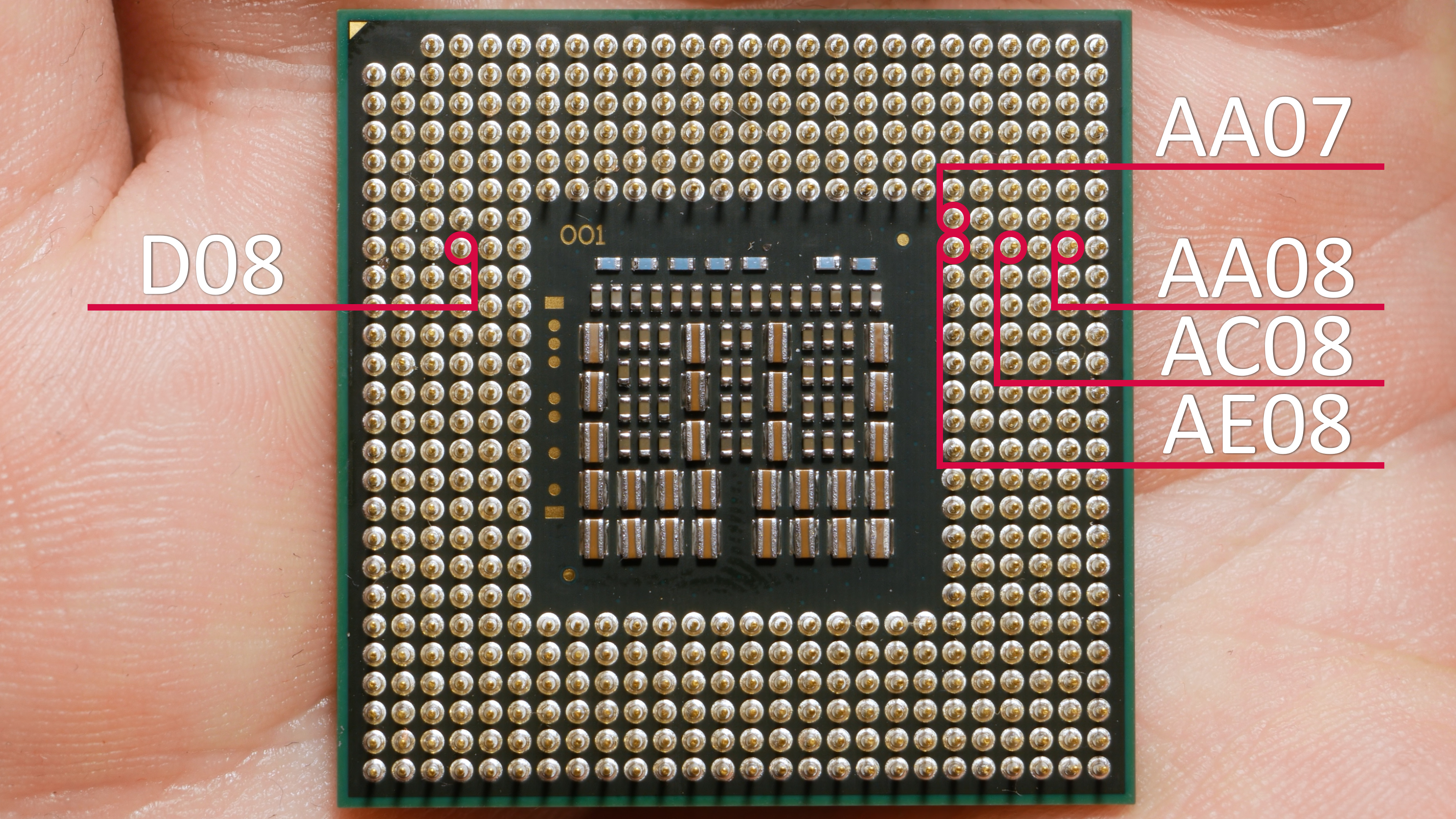
Figure 1
Mobile core2 quad chips use the same socket (Socket P aka mPGA478MN) as most the regular mobile core2 duos of the time. This means most laptops should be in theory capable of using the core2 quad too. Unfortunately there are a few differences in the pinout of the regular core2 duos and core2 quads. From my experience it’s only six pins that need to change.
It's good to note that there were many similar sockets from around this time. Wikipedia has a small segment about it here.
We will only be concerning ourselves with socket P motherboards. Currently I have two laptops at my disposal that use Socket P. One being the tried and true Thinkpad T400. The methods for installing a core2 quad in one of these is well understood at this point. I will include the steps here for the sake of completeness.
First we must isolate five pins on the cpu. The most common method used for this (and the method which will make the cpu viable for other socket p systems) is removal of the five pins. They are D08, AA07, AA08, AC08, and AE08. Some people prefer to use small pieces of heat shrink on the pins and drill out the holes in the socket to accommodate the larger object insertion. I don’t have any drill bits that precise or heat shrink that small so I just broke them off (savagery, I know). The pins to remove are labeled in figure 1.
For the reader’s edification I will also include the pinouts of the T7600 and the Q9000 here as well to compare the differences.
pinout of t7600
pinout of mobile q9000
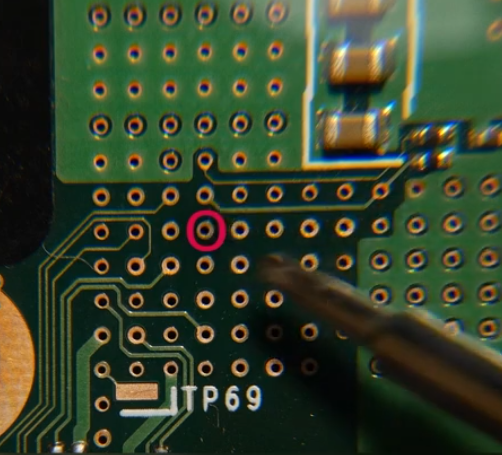
Figure 2 : Pin D22 on the Thinkpad W500 Motherboard
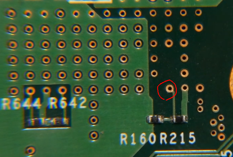
Figure 3 :The source of the reference voltage for D22
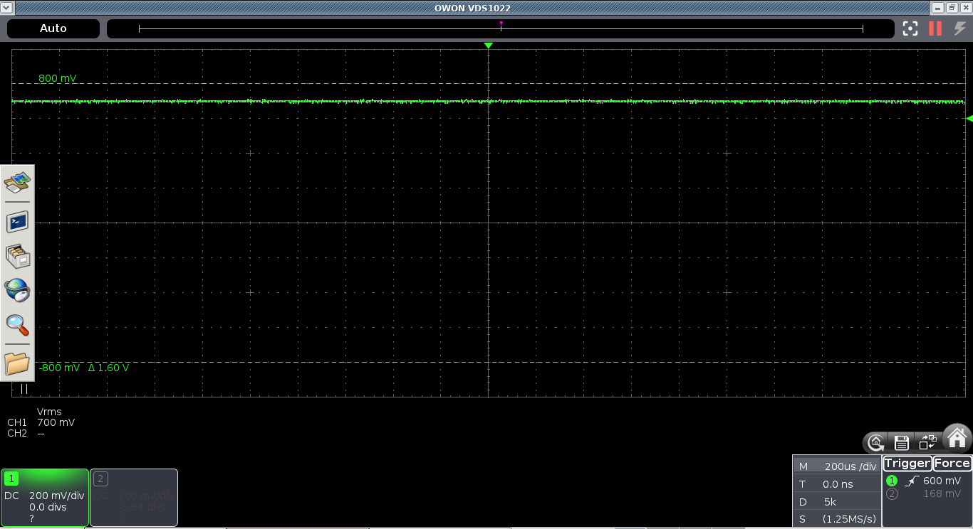
Figure 4 : The voltage measured at D22 on the Thinkpad
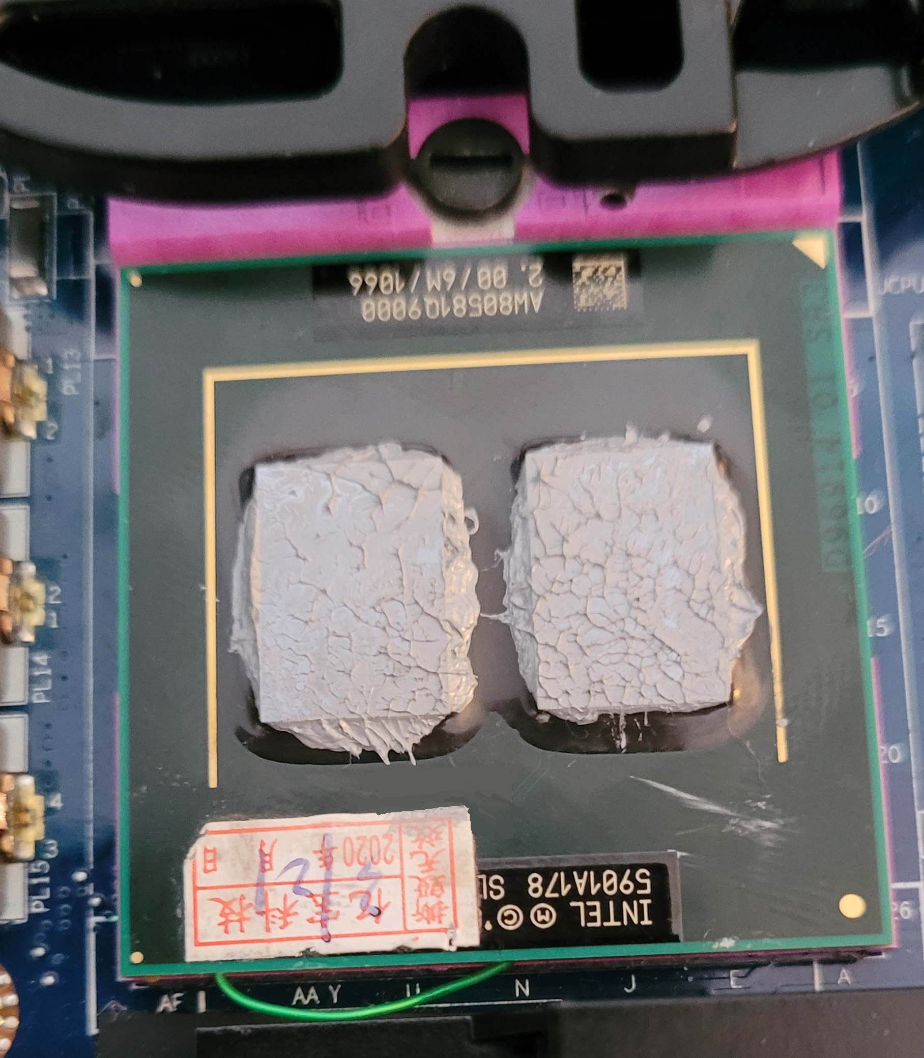
The CPU in situ
The last modification needed will have to be done to the board itself. This is because D22 on a quad core cpu requires a reference voltage to insulate the cpu logic of the second die from electrical noise. This pin is marked as reserved on the T7600 and so if we have multi-core mode disabled on a normal unmodified board the modified quadcore will boot as a single core cpu. Enabling multicore mode on a system with a modified core2quad without the reference voltage on D22 will cause the system to lock up once the second die tries to do anything.
On the Thinkpad there are two handy resistors already on the board that act as a voltage divider which creates the voltage we need for D22. Our source pad for D22 lies between resistors R160 and R215, it is shown in figure 3. Figure 2 highlights pin D22 from the back of the motherboard. On either a T400, or a W500 placing a wire between these two points will have you a working system running on a core2quad.
Of course you will also need to replace the original system bios since closed source firmware sucks and the original Thinkpad bios does not support more than two cores. You can read more about that on my page about Libreboot and coreboot.
Unfortunately this seems to be all the information I can find on running the core2 quad on any socket p system. However I believe that running the core2 quad in any socket p system is possible. The other socket p system I have on hand right now is the Dell Latitude e6400. I may not be the smartest guy around so sometimes when I see something that looks like it will fit I tend to give it a try. One day after upgrading my T400 from a q9000 to a qx9300 I had pulled my Dell latitude apart to flash Libreboot onto the bios chip. While I was there I decided to see what would happen if I put the modified q9000 into the socket on this Dell. To my surprise the laptop booted to the bios and would run Linux if I disabled multi-core support in the bios. So then it seems all we need is that core isolation reference voltage to by supplied to D22 on the Dell and then all should be well.
But what voltage is being supplied to D22? I found no information online about the needed voltage so I did a little testing and reading of my own. On the Thinkpad T400 we use the voltage stolen from the pad between R160 and R215 on the back of the motherboard. I took apart my laptop again and measured the voltage there to be 700mV (seen in figure 4). So we know that we need to feed 700mV into D22 on the Dell, where can we pull that voltage from? According to the T400 schematic I found online R160 is fed power from VCC1R05B.
In the Thinkpad mod the via that the wire is soldered to goes off to pin AD26 on the cpu which is labeled as GTLREF, this means that the mod is simply using the existing GTLREF voltage for both dies instead of using a separate isolated reference voltage for GTLREF2 on D22. This seems to work just fine however. So for any core2 quad cpu to work in any socket p system it seems that we just need to find a way to recreate the connection between pin AD26 and D22 seen on the Thinkpad mod along with the pin isolations on the cpu. Simple, right?
Surprisingly; yes. A simple jumper wire inserted into the pins in question under the cpu provides the needed 700mV isolation reference voltage and we now have a working core2 quad in a Dell Latitude e6400. Seen in figure 5.
And so to summarize: remove pins D08, AA07, AA08, AC08, and AE08 from the cpu. Run a jumper between D22 and AD26. Install Coreboot/Libreboot. With those three steps out of the way any socket p system can use a core2quad.
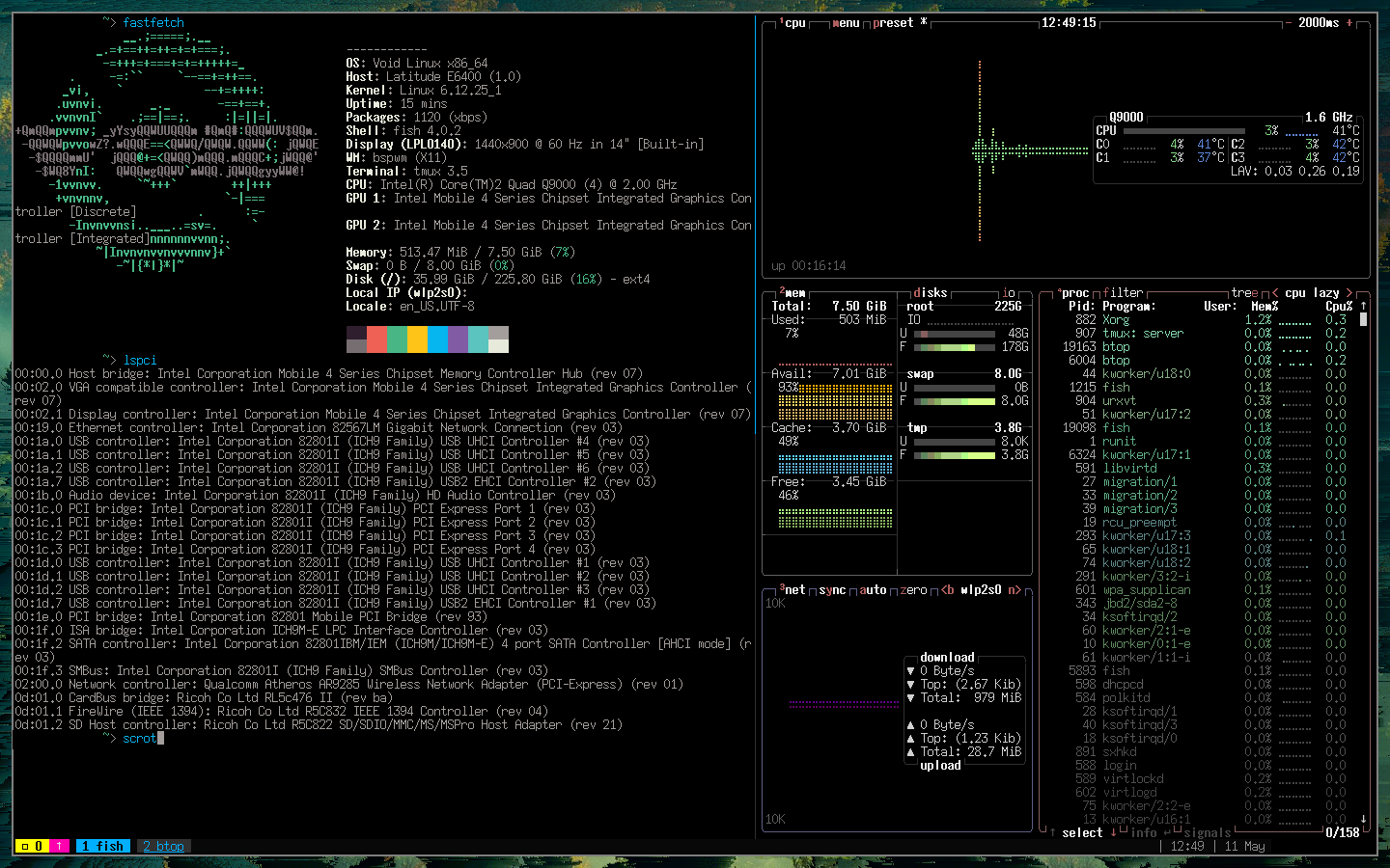
Figure 5 :The end result.